Sunday 29 January 2017

Circuits And Systems [semester-2]

CIRCUIT AND SYSTEMS:


ELECTRIC_CIRCUIT [8th Edition] by NILSSON / RIEDEL [pdf Download Link:   https://goo.gl/O6DsfW


Solution Manual ELECTRIC_CIRCUIT [8th Edition] by NILSSON / RIEDEL [pdf Download Link: https://goo.gl/J3QhJY

Introduction_to_Electric_Circuits_Edition_9 Dorf & Svoboda: https://goo.gl/VuA3IG

Download PsPice Software : https://goo.gl/p8QK7z

Download PROTEUS Software : https://goo.gl/qYWCOM

Digital_Logic_Circuit_Analysis_and_Design.pdf Download Link: https://goo.gl/8qZiNj


What Is Electric Circuit?


 An electric circuit is a path in which electrons from a voltage or current source flow. The point where those electrons enter an electrical circuit is called the "source" of electrons. The point where the electrons leave an electrical circuit is called the "return" or "earth ground".


What is Circuit Engineering?


Electrical engineering is an exciting and challenging profession for any one who has a genuine interest in, and aptitude for, applied science and mathematics. Over the past century and a hall, electrical engineers have played a dominant role in the development of systems that have changed the way people live and work. Satellite communication links, telephones, digital computers, televisions, diagnostic and surgical medical equipment, assembly-line robots, and electrical power tools are representative components of systems that define a modern technological society. As an electrical engineer. you can participate in this ongoing technological revolution by improving and refining these existing systems and by discovering and developing new systems to meet the needs of our ever-changing society. As you embark on the study of circuit analysis, you need to gain a feel for where this study fits into the hierarchy of topics that comprise an introduction to electrical engineering. Hence we begin by presenting an overview of electrical engineering, some ideas about an engineering point of view as it relates to circuit analysis and a review of the international system of units. We then describe generally what circuit analysis entails. Next, we introduce the concepts of voltage and current.We follow these concepts with discussion of an ideal basic element and the need for a polarity reference system. We conclude the chapter by describing how current and voltage relate to power and energy.


In this book, linked above, you would be able to read and understand 


  • Circuit Variable
  • Circuit Elements
  • Simple Resistive Circuits 
  • Techniques of Circuit Analysis
  • The Operational Amplifier
  • Inductance, Capacitance, and Mutual Inductance
  •  Response of First-order RL and RC Circuits
  • Natural and Step Responses of RtC Circuits
  • Sinusoidal Steady-State Analysis
  • Sinusoidal Steady-State Power Calculations
  • Balanced Three-Phase Circuits
  • Introduction to the Laplace Transform
  • The Laplace Transform in Circuit Analysis
  • Introduction to Frequency Selective Circuits
  • Active Fitter Circuits 606 Fourier Series
  • The Fourier Transform
  • Two-Port Circuit 


ELECTRIC_CIRCUIT [8th Edition] by NILSSON / RIEDEL [pdf Download Link:   https://goo.gl/O6DsfW


Solution Manual ELECTRIC_CIRCUIT [8th Edition] by NILSSON / RIEDEL [pdf Download Link: https://goo.gl/J3QhJY
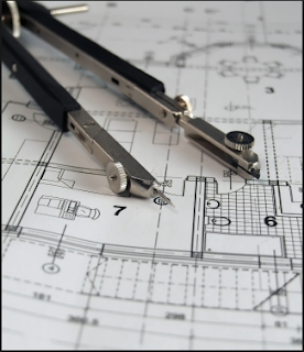


Engineering Drawing [semester-2]


Engineering Drawing [lecture_1] pdf: https://goo.gl/qZRabf


ENGINEERING DRAWING


Engineering Drawing is very important field of any engineering, engineering drawing or simple ED is the concept, idea and information about a solid object, that may be a car, home, computer, robotics, communication, computer science, chemical, textile, transportation, automobiles, architectural, and it will be easy to say any type of engineering.

According to the wikipedia:
"An engineering drawing, a type of technical drawing, is used to fully and clearly define requirements for engineered items.
Engineering drawing (the activity) produces engineering drawings (the documents). More than merely the drawing of pictures, it is also a language—a graphical language that communicates ideas and information from one mind to another. Most especially, it communicates all needed information from the engineer who designed a part to the workers who will make it."
We sketch and design an object from different angles, describing it with different specific combination of lines, arcs and circles and other shape sketches, in-fact it is a 2-D diagram of describing almost all the properties of the object.

Is ED an Engineering Language?

Engineering Drawing is the Language of Engineers. A drawing drawn by an Engineer, having Engineering knowledge, for the Engineering purposes is an Engineering Drawing. It is very important to learn Engineering Drawing because it is a starting point of all Engineering branches-Mechanical, Production, Civil, Electrical, Electronics, Communication, Computer Science, Chemical, Textile, Transportation, Metallurgical, Instrumentation, Automobile, Architectural, Agricultural, Aeronautical, Marine, Mining Engineering etc.

It is the Universal Graphic Language of Engineers, spoken, read and written in its own way. Every language has its own rules of grammar. Engineering drawing also has its grammar in the theory of projections, its idioms in conventional practices, its punctuations in the types of lines, its abbreviations, symbols and its descriptions in the constructions. It is up to engineer, what angle he wanna chose for describing his diagram or design best, and what he or she thinks, is better.

Students should not get confused Engineering Drawing with Artistic Drawing. The latter is commonly used by the artists for commercial purposes, such as in painting, advertisement boards, etc.

Geometrical Drawing:
Geometrical drawing is the foundation of all Engineering Drawings. It is a subject, difficult to learn or to teach without the aid of a good text book. A good speed in drawing work should be achieved, because "time is money" in the industry. Accuracy, neatness and legibility are of great importance in engineering drawing.

Geometrical Drawing consists of:
1.       Plain Geometrical Drawing and
2.       Solid Geometrical Drawing.

Geometrical drawing is the art of representation of geometrical objects such as square, rectangle, cylinder, cone, sphere etc. on a drawing sheet or paper.

Plane Geometrical Drawing is the art of representation of objects having two dimensions or 2-D structures, i.e., breadth and length such as square, rectangle, quadrilateral etc. on a drawing sheet, paper or board.

Solid Geometrical Drawing is the art of representation of objects of three dimensions 3-D structures, i.e., length, breadth and height, such as cube, cylinder, sphere etc. on a drawing sheet, paper or drawing board.

Engineering drawing, particularly, geometrical" drawing is the basis for various specialized types of drawings applied to various fields MACHINE DRAWING in the machine industries ; STRUCTURAL DRAW¬ING in the structural constructions such as buildings, bridges and dams; ELECTRICAL DRAWING in the electrical industries ; AERONAUTICAL DRAWING in the aircraft manufacturing ; MARINE DRAWING in ship construction and so on.


Differential Equations [semester-2]


Download Now: 

 Advanced Engineering Mathematics_by_ERWIN KREYSZIG_9th Edition

Solution Manual:

Solution Manual of Advance Engineering Mathematics